
This tutorial will walk you through on how to create control rig assets that enable you to adjust your character spine using mouse input, working then as an aim offset. And on how to adjust your character hand positioning to create sweep and stabbing motions using spears or staffs. It also provides you the tools to repurpose and recreate for other types of weaponry and motions.
First it will show on how to create a Control Rig asset, it will provide a step by step to create the spine influencing asset and compounding from it the hands influencing Control Rig will be shown. This tutorial follows the usual UE4 skeleton naming scheme and hierarchy.
Requirements:
- Control Rig plugin.
- Full Body IK plugin.
- Engine version 4.26 or above.
After this tutorial you will have two control rigs that enable you to apply runtime adjustments to your character spine or hand positioning as shown on the next two videos.
1 – Creating the Control Rig asset
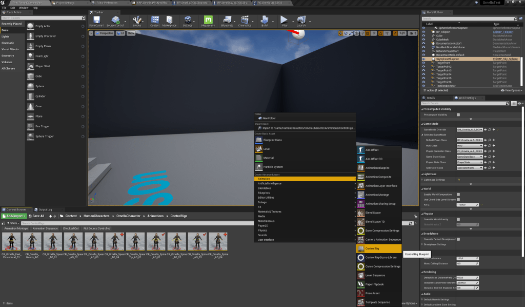
To create your control rig asset you just need to right click on the content browser then go to “Animation” and then select “Control Rig”, see Figure 1. The editor will then prompt you to select the parent rig. There should only be a single option named “ControlRig”. Select it.
Afterwards, opening your newly created asset you will see a window like in Figure 2. To start building your Control Rig you first need to import a skeleton hierarchy. In order to do it, click on the green button named “Import Hierarchy” at the middle of the left side of the window. And then select the desired skeletal mesh.
Note: The Control Rig is neither importing the skeleton nor the skeletal mesh itself. It’s creating a copy taking into account the skeleton hierarchy. So it takes into account the existing bones’ names and the corresponding transforms. The control rig asset won’t be referencing the skeleton at all, as it can be verified using the reference viewer.
After that you will have your skeleton hierarchy imported and the selected skeletal mesh will be on the viewport as in Figure 3.

2 – Adding controls and spaces to Control Rig
In order to better understand the work that will be done it is best to provide a brief explanation on what Controls and Spaces are:
- Controls: they are points on the rig global space that you can use to aid or directly adjust bones’ transforms.
- Spaces: they work as being a secondary frame of reference to any child control (or space) that it parents. Meaning: on control rig the global space origin (0,0,0) is located at the root bone. When you create a space, you are creating a new reference frame for any child of this new space. So their global transform is measured from the rig global whilst the local transform is measured from the parent space.
So to create either a space or a control one can right click on a bone and select “New” and then “New Control” or “New Space”. It can also be done on a blank area at the bottom of the “Rig Hierarchy”, so after the root bone chain. Let’s create a control like that.
A red sphere should appear at the root bone position. Rename this new control to “root_ctrl”. The naming scheme is following the UE4 mannequin scheme, if your skeleton has a different naming convection just adjust the names and follow them by the following suffixes: “_ctrl” if it is meant as a control or “_space” for spaces.
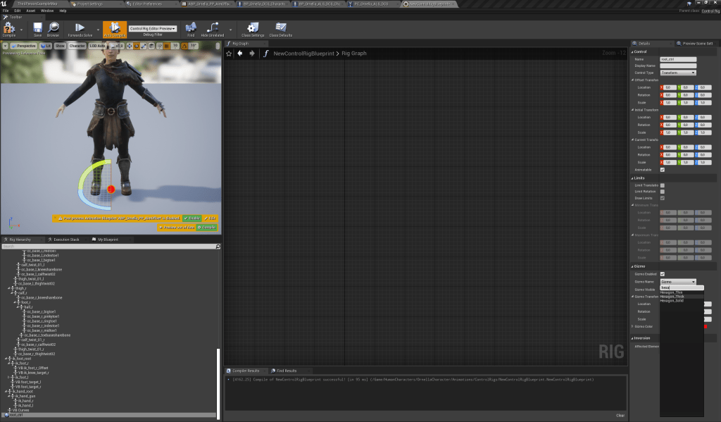
The red sphere is a gizmo, it’s just a visual representation of the control that was created. While having it selected, on the right side, on Gizmo section, you can adjust its transform, colour, and type. Change it to a hexagon (see Figure 4 for reference).
Note: spaces do not have gizmos.
Following that, click on the “root_ctrl” and create two more controls named “foot_r_ctrl” and “foot_l_ctrl”. Change the gizmos to boxes and colour the left one to blue (left sided controls will be coloured blue while right side is coloured red). Similarly create a space named “spine_02_space” and parented to this space create a control named “spine_02_ctrl”. Change the “spine_02_ctrl” gizmo to a yellow circle.
All gizmos should be appearing on top of each other. To reposition them on the “Rig Graph” right click and write “Setup Event” and select it. This is the event that runs before the other events. Think of it as a construction script.
Then, on the graph you can place a “Children” node, just right click and search the name. This node can help you to recursively obtain the entire chain of the type of items you want (including the parent). If set to search for controls and there’s a space on the chain, it will jump those. So in our case it will retrieve the root and feet controls as a single collection. A collection is just a container for bones, controls, and spaces.
We want to set up the controls initial positions as being the respective bones initial positions. For that we can iterate through the created collection using a “For each item” loop node. Expanding the “Item” node you can see that there is a “Name” pin. From it create a “Chop” node, this node is meant to remove substrings with the length specified. Since using our naming convection we can obtain the bones’ names by chopping the item name by a length of 5 (so removing the “_ctrl” suffix). From the remainder we create a “Get Transform” node, set it up to bone type and to retrieve the initial transform from the global space. From this transform we set up a “Set transform” node, the conditions are: “Initial” and “Propagate to children” as True. Also, link the “Item” pin from the loop node to this node. This finishes the positioning of the control in the collection. It should look like it is in Figure 5.

Then we just need to setup the “spine_02_space” and his child control. Since we want to have both the space and control initial location to coincide with the “spine_02” bone we just require to setup the space, as the child control will be at (0,0,0) in local space which is where the “spine_02_space” will be located. For that we just need to retrieve the “spine_02” bone initial location. Place a “Get transform” node, set it to retrieve the initial bone transform and then expand the pin and get just the “Translation” pin. From it place a “Transform from SRT” node. It will create a transform from the fed in values. So the initial location will be in, and it will also make the rotation to be (0, 0, 0). Since later we will be adjusting the rotation at runtime it is best to work with it starting at 0. From this transform place a “Set Transform” node and set it up to set the initial transform of “spine_02_space”. As per Figure 6.

Having finished the setup event you can check that all the controls should be placed on the correct bones as in Figure 7.

3 – Setting up the Spine influence.
Now that the rig is properly done let us move to the setup to influence the spine. For it to work you’ll need to place a “Forwards Solve” node. This is a node that is meant to be read as: you set up the controls’ positions and then move the bones along adjusting if necessary.
One important note to take is the following: the sequence at which you apply or adjust the controls positioning matters. For example in a parent/child relationship of a space and control: if you first setup the control transform but then change the parent space transform you will be inevitably altering the control positioning. So be aware of that.
Since there will be quite a few steps to do let’s first place a “Sequence” node. From it the first two execution pins will just mimic the “Setup Event”, we just won’t be setting the initial transforms. So on the first execution pin just paste the setup for the space transform, same as before barring setting “Initial” to false. Then on the second pin paste the loop we had done before. But now we also want to setup the “spine_02_ctrl” to follow the “spine_02” bone. So for that, on “Rig Hierarchy” click on the control and drag it to “Rig Graph”, when prompt select the last option “Create Collection”. Now you will have two collections, one with the “root_ctrl” chain and then one with just “spine_02_ctrl”. From one of them, drag the “Collection” pin and select “Union” this allows you to merge two collections into one. Then drag the resulting pin to the “For Each Item” loop node. Remember to toggle all “Initial” options to false.
This two parts are just there to assure that your rig controls will be following the bones when they get animated.
Now we can inject the logic behind the spine influencing. The ideia behind it is simple, we will adjust the “spine_02_space” transform and the “spine_02_ctrl” will follow it by being a child of it.
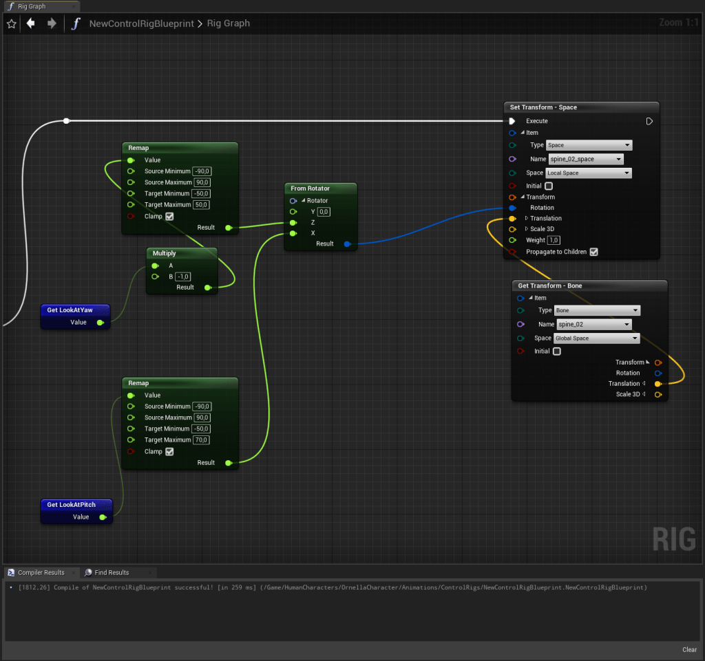
From the “Sequence” node third execution pin you place a “Set Transform” node, setup it up to be applied on “spine_02_space”, set “Space” as “Local Space” and “Initial” to false. Now you will want to pass along a “Rotation” value. It will be this value that will come from mouse input. At the right side of “Rig Hierarchy” you will notice that there is a “My Blueprint” tab, on it you can create variables as you can on every blueprint. Create two float variables that are meant to store the yaw and pitch input values. And when creating them click on the eye icon next to them, it will allow you to then use the values as inputs when setting up the Control Rig in an animation blueprint.
Now drag those variables to the “Rig Graph”.
Dragging the pins from those variables create “Remap” nodes. These are just so you can map the input values to the values you might want to rotate the space by. You will have to adjust these values by trail and error. From the “Remap” nodes create one “From Rotator” node, place the values on the Z and X values and then the resulting rotator gets fed in the “Set Transform” node. The location is taken from the “Get Transform” from the “spine_02” bone. You will end up with something similar to what is shown on Figure 8 (the “Multiply” node shown there is due to how the Yaw value is being calculated on another blueprint).
And for last there is just the need of a “Full Body IK” node, this node will take the controls’ transforms as constraints and then will solve the skeleton positioning adjusting the skeleton pose as needed. For a more thorough explanation it might be best to search for “Inverse Kinematics”.
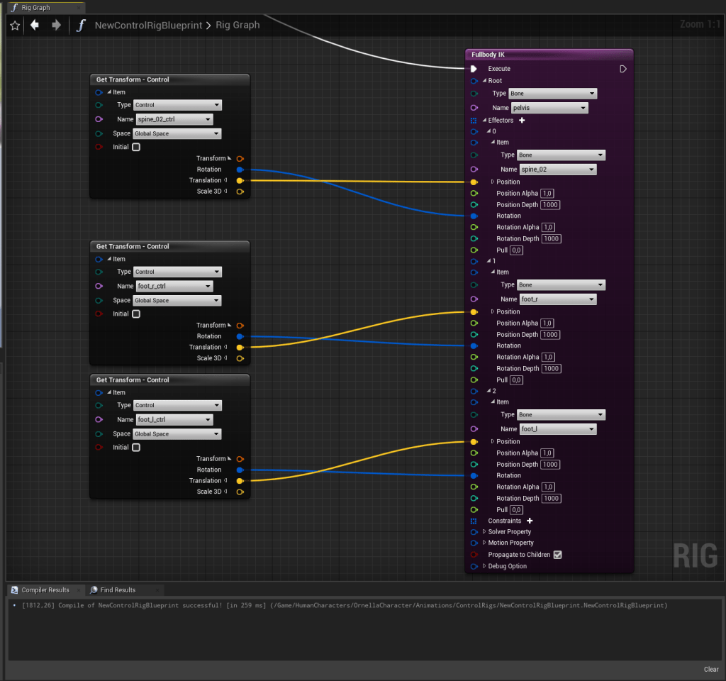
So, placing a “Full Body IK” node as stated, there will be a “Root” pin, on it just setup up the root bone of the required chain, in this case let’s use the “pelvis” bone. There will also be an “Effectors” pin with an add symbol besides it, click that to add effector entries. Create three of them and set them up to be the “spine_02”, “foot_r” and “foot_l” bones. Now we need to get all the needed controls’ transforms. On the “Rig Hierarchy” and while holding the control key, click on “spine_02_ctrl” and both feet controls, drag to the “Rig Graph” and select “Get Transforms”. Now expand the transform pins and just drag the “Translation” and “Rotation” to the correct pin entries on the IK node. When you drag one pin the valid entries will light up. Correspond the control transforms to the correct bones. The result should look like Figure 9.
If the “spine_02_ctrl” gizmo is rotated, probably upwards, adjust its rotation on the corresponding gizmo menu, something like Y = 90 should suffice.
4 – Setting up the Hands influence
The setup for this Control Rig is quite similar to the previous one. The only differences are that we will be creating a space to control the hands that will require to be always between both hands, creating controls for both hands and there won’t be a need for spine controls.
So for that, create a similar “root_ctrl”, “foot_r_ctrl” and “foot_l_ctrl” as before. Also same gizmo setup. Then create a space called “hand_center_space” and create two controls named “hand_r_space” and “hand_l_space”. For these controls’ gizmos use “Circle_Thick” and remember to colour the left one as blue.
The “Setup Event” will also be similar, same loop logic for the root control chain just need to merge with a collection of both hands’ controls.
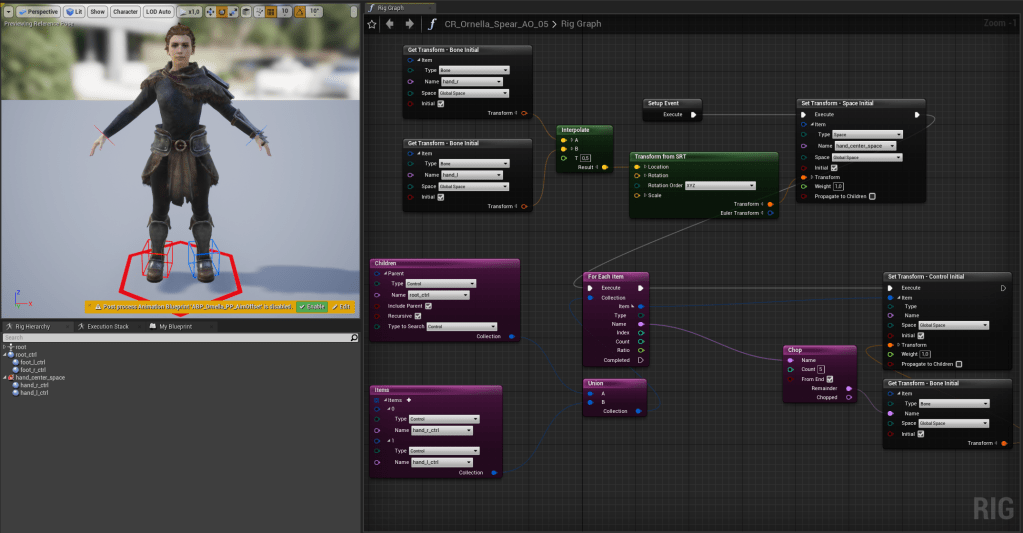
Now the “hands_center_space” will have the requirement of being at the middle point of both hands. For that, get the transform nodes of both bones and from the “Translation” pin add an “Interpolate” node with a “T” value of 0.5.
This will ensure that the resulting vector will be at the middle point of both hands. Feed this resulting vector to a “Transform from SRT” as the previous rig. The result should look similar to Figure 10.
Now, for the “Forwards Solve”, same as before. Following the first two execution pins of a “Sequence” node place both parts of code from the “Setup Event” but now with the “Initial” boolean turned to false.
For the third execution pin we will be setting up our hand influence. Just as before we will be adjusting the space transform which in turn will adjust the child controls. On this setup we will be creating a sideways sweep and a stabbing motion. The sweep motion is just a matter of adjusting the rotation value of the space by the Yaw value that we pass to the Control Rig. While the stabbing motion will take as an input the Pitch value.
As before, create two float variables for these values. Then from the Yaw value place a multiply node before the “Remap” node. This multiply node will aid in adjusting the speed of the motion. Pass the remapped value to a “From Rotator” node and the result to the “Rotation” pin of the “Set Transform” node.
For the “Translation” value we will still be taking into account the middle point between both hands but then we will be adding a value to the Y positions. So this would offset the position forwards and backwards on our setup. So from the same interpolate setup as mentioned before, pass the split the “Translation” pin from the “Transform from SRT” node and then pass the X and Z values directly to the “Set Transform node”. The Y value will go to an “Add” node.
The second “Add” pin will be fed with our Pitch value. Pass the Pitch variable through a “Multiply” node (again to work as a speed multiplier, so adjust the value to your taste) then trough a “Remap” node and from it to the “Add” node and this result to the Y input of the “Translation” on the “Set Transform” node. The result should be similar to Figure 11.

Now it’s just a matter of adding the “Full Body IK” node, still having the root bone being the pelvis but now the effectors are both the feet and hands bones. Get the corresponding control transforms and set them up accordingly. It should look like as in Figure 11.

5 – Placing your Control Rig on an animation blueprint.
To use your Control Rig on an animation blueprint just place a “Control Rig” node on the blueprint, then on “Control Rig Class” choose your newly created rig and to enable your variables just toggle the “Use pin” checkboxes. See Figure 13.
For mouse input you can pass the usual variables that are also used to drive standard aim offsets or blendspaces.

6 – Final considerations
Thus this concludes the tutorial. It should provide some basic notions on how to create your own control rigs for a multitude of end results or mechanics you so desire.
One thing that was not previously explained is the why do you need to also set up feet controls. The reason behind it is that otherwise, when applying the IK node you would be adjusting the feet positioning. By using controls that follow the feet as constraints you assure that the final pose will still follow the feet animation and thus not creating extreme rotations on the rest of the body that could be hard to blend or layer out on the animation blueprint.
The other point is that, in order to enable your character to drive the Control Rig as in the sample videos shown at the beginning you have to do two things: on the spring arm component set “Use Pawn Control Rotation” to False and on your movement component set the “Rotation Rate” to (0, 0, 0). It likely has only a value on the Z axis, so just set that one to 0.
For further references see the following links to Epic Games’ documentation and video on the subject:
Control Rig Epic’s documentation.

Leave a comment